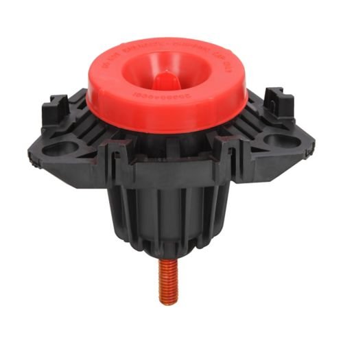
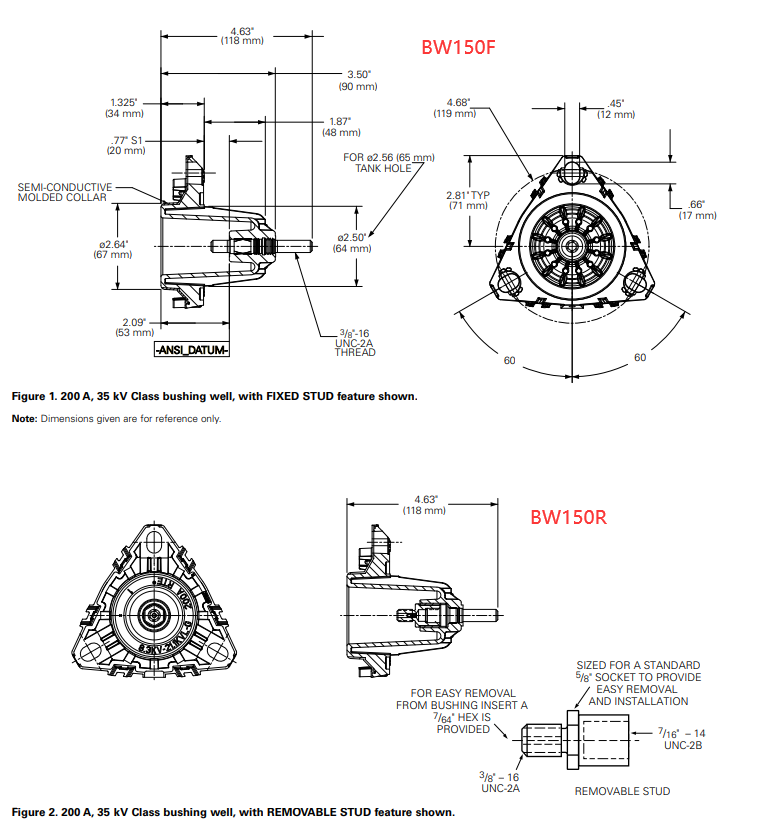
Eaton Cooper Power Systems’ Bushing Well models BW150R (Removed) and BW150F (Fixed) are mainly used for bushing connections in high-voltage electrical equipment such as transformers and switchgear. The core differences between the two are installation methods, maintainability, and applicable scenarios. Here is a detailed comparison:
1.Comparison of Electrical and Mechanical Parameters
- General parameters (both consistent):
- Rated voltage: 15 kV (“150” represents the 15 kV level).
- Current capacity: usually 600A or 1200A (specific model to be checked).
- Insulation material: epoxy resin or silicone rubber.
- Differences:
- The fixed flange of BW150F may provide higher short-circuit withstand capability (due to larger contact area).
- The insertion and removal times of BW150R are limited (such as 500 cycles, please refer to the specification sheet)

2.Detailed functional differences
(1)BW150R (Removed)
Design features:
Adopting detachable interfaces (such as buckles, threads, or quick release mechanisms) to facilitate the replacement of sleeves or maintenance without power outages or minimizing downtime.
Usually equipped with elastic sealing rings to ensure sealing even after multiple disassembly and assembly.
Typical applications:
Substation switchgear that requires regular testing or replacement of sleeves.
Modular designed mobile transformers or temporary power equipment.
(2)BW150F (Fixed)
Design features:
Fixed by flange bolts, usually not disassembled after installation, relying on static sealing (such as epoxy resin or metal gaskets).
The structure is simpler, the electrical contact is more stable, and it is suitable for long-term high load operation.
Typical applications:
Permanent installation of power transformers or GIS (gas insulated switchgear).
In high vibration environments (such as power plants), it is necessary to avoid the risk of loosening.

3.Selection suggestions
Choose BW150R if:
The equipment requires frequent maintenance (such as backup power supply for data centers).
Space is limited and quick disassembly is required (such as for offshore wind power platforms).
Choose BW150F if:
Pursuing long-term reliability (such as power grid backbone transformers).
The environment is harsh (high humidity, high vibration), requiring anti-corrosion design.
4.Precautions
Sealing aging: The dynamic sealing of BW150R needs to be checked regularly to avoid leakage caused by multiple disassembly and assembly.
Torque requirement: When installing BW150F, it is necessary to strictly apply bolt torque according to the manual to prevent over tightening and damage to the flange.
Compatibility: The interface sizes of the two may be different, and compatibility needs to be confirmed when replacing (such as sleeve diameter, flange hole spacing).
5.Key Differences Summary
| 1. Key Differences Summary | ||
| Feature | BW150R (Removed) | BW150F (Fixed) |
| Mounting Type | Removable(Easy maintenance access) | Permanent fixed installation |
| Application | Equipment requiring frequent maintenance | Long-term stable installations |
| Sealing | Dynamic sealing (reusable) | Static sealing (higher reliability) |
| Mechanical Strength | Slightly lower (due to removable design) | Higher (flange provides robust support) |